Finite element analysis model of rotary forging for assembling wheel hub bearing assembly – Post 2
페이지 정보
작성일posted onLink
본문
Finite element analysis model of rotary forging for assembling wheel hub
bearing assembly – Post 2/2
This post is in continuation with last week’s post on the finite element analysis model of rotary forging process of a wheel hub bearing assembly. Adding on to that introductory post, the details of the analysis model and the predictions will be discussed in this post.
This
kind of rotary forging processes requires higher computational times using a
full domain analysis model because they have pretty larger strokes compared to conventional
forging. It should be noted that the plastic deformation occurs due to a localized
contact of the forming die with material in the early stage, implying that the
plastic deformation has a restricted effect on the neighborhood of the local
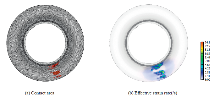
contact region. This fact can be observed from Figure 1, indicating that the
contact region during rotary forging for assembling a wheel hub bearing
assembly is quite small.

Figure 1: Contact area during rotary forging
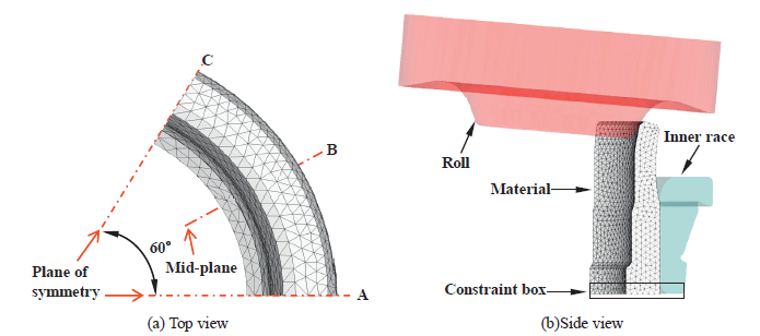
Therefore, as shown in Figure 2, a partial analysis model defined by two artificial planes of symmetry is proposed for the engineering analysis model, which was successfully applied for simulating a flow forming process (Cho et al., 2011). Of course, it is noted that the analysis results of this model may be more or less different from the real phenomena, especially at the planes of symmetry. However, it can be expected that quite reliable predictions can be obtained for the present rotary forging process because the plastic deformation occurring at the local contact area has little influence on that at the opposite side as shown in Figure 1, emphasizing that the effective strain rate distribution is concentrated around local contact area.

Figure 2: Finite element analysis model for the 60° analysis model
To check validity of the proposed approach, a rotary forging process of Figure 2(a) was analyzed, which was previously studied using a hexahedral element (Moon et al., 2007). The shape of a preform and its dimensions are shown in Figure 4(b). The lower part of the preform is far away from being plastically deformed and its displacement was constrained by a constraint box in which all nodal degrees of freedom of the nodes are constrained.
The flow stress was defined by
The upper die revolves without any power exerted and the friction between the upper die and material was thus neglected. If the friction is considered, the revolving velocity will become an unknown variable, which may enhance a negligible part of solution accuracy at a greater expense of computational time.
Figure 2 is a 60° analysis model, which is composed of two artificial planes of symmetry, a part of material defined by them, a constraint box and tools or dies. First, to reveal the size effect of the analysis domain defined by two planes of symmetry, 30°, 60° and 90° analysis models were investigated.
Figure
3 shows the predicted configurations of the deformed material together with the
inner race of hub bearing unit at the selected planes for the 60° analysis
model. As shown in the figure, there exists a non-negligible difference in
deformed shape of material around the bent region between the mid-plane and
symmetric plane. It can be seen that change of the shape is stationary round
the mid-plane between 20° and 40° planes, implying that the mid-plane is quite
far away from the effect of the assumed artificial plane.


Figure 4:
Deformation history for the 60° analysis model
Figure 4 shows the history of deformation of sections A and B for the 60° analysis model. It can be seen at a glance that the deformation history of section A is nearly the same with that of section B as a whole. However, around the final stroke a distinct difference in contact region between the two planes can be observed. It is noteworthy that the size of cavity formed between the hub and inner race of hub bearing has a strong influence on the forming load when the process is controlled in terms of displacement (Shim et al., 2012) because the free surface around the major deforming region becomes very small at the final stroke.

Figure 5. Comparison of mid-planes of the 30°, 60° and 90° analysis models and experiments
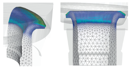
Figures 5(a)-(c) compare the deformed shapes at the mid-plane for the 30°, 60° and 90° analysis models, indicating that all the predictions are nearly the same. Comparison of the predictions in Figures 5(a), (b) and (c) with the experiments in Figure 5(d) shows that they are acceptable. Less than one hour of computational time was taken for the 60° analysis model. Figure 6 shows the predictions obtained by the 60° analysis model at the final stroke with emphasis on finite element mesh system used.

Concluding remarks:
A computationally efficient finite element analysis model was proposed for analyzing a rotary forging process. The model is composed of one or two artificial planes of symmetry and a part of material defined by them. The model assumes that plastic deformation is concentrated on relatively small contact area and was employed for simulating a cold rotary forging process of a wheel hub bearing assembly, after local contact area was found to be very small, which is a typical application example of the proposed analysis model. The simulation was conducted using a rigid-plastic finite element method assisted by an intelligent remeshing technique.
Three cases of 30°, 60° and 90° analysis models were studied to validate the present finite element analysis model. The predictions at their planes of symmetry and mid-planes were investigated and compared with the experiments, revealing that the predictions at the mid-planes are in good agreement with the experiments for all the cases while those at the planes of symmetry are more or less different from the actual phenomena. Based on the discussion about the predictions, the 60° analysis model is recommended for both computational efficiency and solution reliability. With the present finite element analysis model, computational time could be reduced drastically.
References:
[1] Cho,
J. M., Jung, Y. D., Lee, M. C., Joun, M. S., 2011.Finite element model of
simulating a chipless forming process based on flow forming. Proceedings of the
Korean Society for Technology of Plasticity, 143-146
[2] Choi,
S., Na, K.H., Kim, J. H., 1997. Upper-bound analysis of the rotary forging of a
cylindrical billet. Journal of Material Processing Technology, 67(1-3), 78-82.
[3] Guangchun,
W., Guoqun, Z., 2002. Simulation and analysis of rotary forging of a ring
workpiece using finite element method. Finite Elements in Analysis and Design,
38(12), 1151-1164.
[4] Han,
X., Hua, L., 2013. 3D FE modelling of contact pressure response in cold rotary
forging. Tribology International, 57, 115-123.
[5] Hawkyard,
J. B., Gurnani, C. K. S., Johnson, W., 1977. Pressure distribution measurements
in rotary forging. Journal of Mechanical Engineering Science, 19(4), 135-137.
[6] Liu,
G., Yuan, S. J., Wang, Z. R., Zhou, D. C., 2004. Explanation of the mushroom
effect in the rotary forging of a cylinder. Journal of Material Processing
Technology, 151(1-3), 178–82.
[7] Moon,
H. K., Lee, M. C., Joun, M. S., 2007. An approximate efficient finite element
approach to simulating a rotary forming process and its application to a
wheel-bearing assembly. Finite Elements in Analysis and Design, 44(1-2), 17-23.
[8] Munshi,
M., Shah, K., Cho, H., Altan, T., 2005. Finite element analysis of orbital
forming used in spindle/inner ring assembly. 8th ICTP, Verona,Italy.
[9] Shim,
G. H., Kim, D. K., Choi, M. H., Kim, E. Z., Joun, M. S., 2012. Proposal of an
optimized forging process for assembling hub bearing unit. Proceedings of the
Korean Society for Technology of Plasticity, 346-349.
[10] Toda,
K., Ishii, T., Kashiwagi, S., Mitarai, T., 2001. Development of hub units with
shaft clinching for automotive wheel bearing. KOYO Engineering Journal English
Edition, 158, 26-30.
[11] Wang,
G. C., Guan, J., Zhao, G. Q., 2005. A photo-plastic experimental study on
deformation of rotary forging a ring workpiece. Journal of Material Processing
Technology, 169(1), 108–114.
[12] Yuan,
S. J., Wang, X. H., Liu, G., Zhou, D. C., 1998. The precision forming of pin
parts by cold-drawing and rotary-forging. Journal of Material Processing
Technology, 86(1), 252–256.
[13] Zhou,
D. C., Yuan, S. J., Wang, Z. R., Xiao, Z. R., 1992. Defects caused in forming
process of rotary forged parts and their preventive methods. Journal of
Material Processing Technology, 32(1-2), 471–479.
Do follow us on LinkedIn to stay updated and know more interesting simulation examples from a wide variety of metal forming processes.

