Effect of friction laws on metal forming simulations – A summary – [1/2]
페이지 정보
작성일posted onLink
본문
Effect of friction laws on metal forming simulations – A summary – [1/2]
The series of two articles, to be published in the coming weeks will be based on the effect of friction formulation on the prediction of metal forming processes.
In
this article, effect of two friction formulations on three processes namely cylinder
compression process with low aspect and contact ratio, cylinder compression
process with high aspect and contact ratio and the hot strip rolling process will
be presented.
Friction is an important factor influencing the outcome of metal forming simulations. The major factors affecting friction are
- Normal stress along the die-material interface
- Lubrication conditions
- Relative velocity
- Temperature
- Roughness
- Mechanical properties of the material / die
As the die-material interface is usually under high pressure and temperature, a detailed investigation of above factors remains a challenge. Traditionally, the Coulomb friction law and the constant shear friction law are used in formulating the friction conditions in metal forming simulation.
According
to the Coulomb friction law, the frictional stress is proportional to the
normal stress or force, while the constant shear friction law states that the
frictional stress is a certain fraction of the shear yield stress of the material
and does not reflect the effects of the normal stress on the frictional stress.
It is clear that frictional stress is related to the normal stress, and that the Coulomb friction law or its variants can describe the real behavior of friction better than the constant shear friction law. However, the constant shear friction law has been widely used in simulations of bulk metal forming due to its theoretical simplicity and numerical rigidity. At room temperature, the two laws give nearly the same results for ring compression because the normal stress distribution in this case is relatively uniform over the contact area even though ring compression itself is very friction- sensitive.
In
this study, the two friction laws are applied on several friction-sensitive
metal forming processes using the rigid-viscoplastic FEM based AFDEX – the intelligent
metal forming simulator.
Friction
evaluation curve:
Ring compression has been widely used to evaluate friction because the ring is very sensitive to deformation under friction conditions. Specifically, the inner and outer radii of the deformed ring vary with respect to its height, and the deformation pattern is highly dependent on the friction conditions. Through finite element analysis, one can construct the friction evaluation curves by plotting the minimum ring radius versus height. For example, Fig. 1 shows the friction evaluation curves for a material with a flow stress of
Thus, ring compression tests can be used to estimate the Coulomb friction coefficient or friction factor by comparing the experimental curve of the minimum ring radius versus height to the theoretical friction evaluation curves. Note that the initial ratio of the outer diameter to the inner diameter to the height of the ring is 6:3:2.
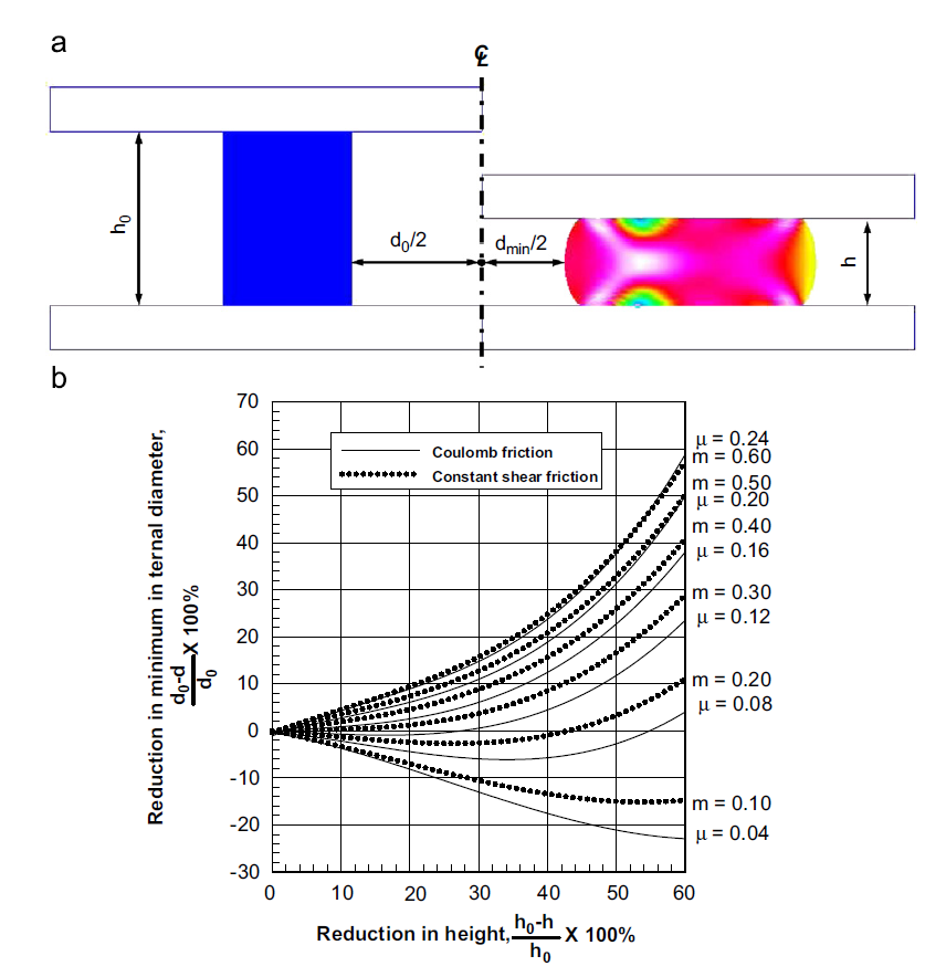
Fig. 1 shows a set of friction evaluation curves at room temperature and Fig. 2 shows the same curves for a material at an elevated temperature, where the flow stress is

To obtain Fig 2, the following conditions were used:
- Initial outer ring diameter: 60 mm
- Ring height: 40 mm
- Punch velocity: -200 mm/s
- Reduction ratio: 60%
Comparing the slopes of the curves in Figs. 1 and 2 show that the Coulomb friction law and the constant shear friction law produce nearly the same results, especially for a smaller reduction and lower friction. However, as friction and reduction increase, the difference in the slope of the friction evaluation curves increases. This is because the Coulomb friction law reflects the normal stress variation at high friction and high reduction, while the constant shear friction law does not.
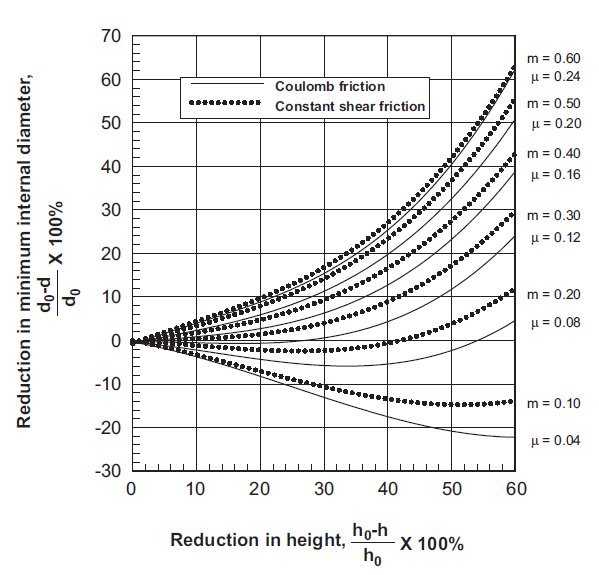
Figure
2: Friction evaluation curves for a material at the elevated temperature,
obtained by ring compression simulation
Before
we move forward, you need to know the following definitions.
- Aspect ratio of the process is defined as the width of the material divided by its height.
- The ratio of the contact region is the area of the die material interface divided by the entire surface area of the material.
The process information that was used to obtain results shown in Figure 2 will be used henceforth for the rest of the processes, unless specified explicitly.
Now let’s have a look at the application of these friction laws for several metal forming processes.
1. Low aspect ratio cylinder compression
Fig. 3 shows the predicted results of metal flow lines formed by compressing a cylinder with a relatively low aspect ratio and a low contact ratio.
Fig.
3(a) shows the results obtained with µ = 0.2, while Fig. 3(b) gives the results
for m = 0.48.
It
can be observed from Figure 4 that the forming load curves also do not have
much of a difference.
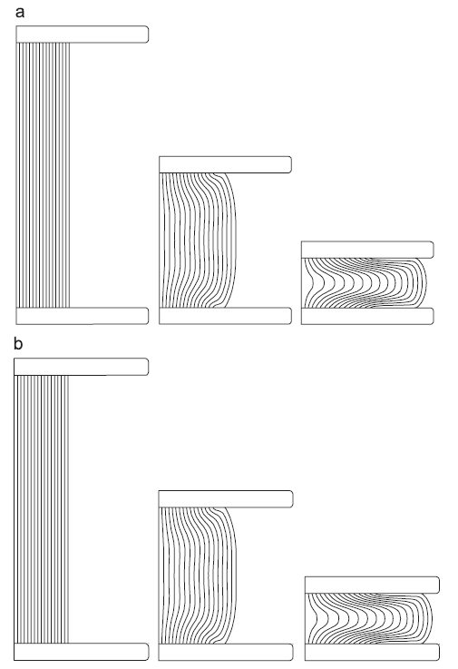
Figure 3: Comparison of metal flow lines formed from compression of the ring with small aspect ratio and small ratio of contact region:(a)Coulomb friction law and (b) constant shear frictional law.
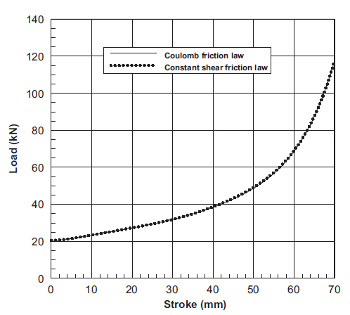
Figure 4: Stroke-forming load curves of the ring compression with small aspect ratio and small ratio of contact region.
In the case of cylinder compression with low aspect ratio and contact ratio, there seems to be not much of a big difference between Coulomb and constant shear friction law model.
2. High aspect ratio cylinder compression
Figures.
5 and 6 show the analysis results of a cylinder compression process when the
aspect ratio of the cylinder is relatively large. Together, these figures
indicate that the results are nearly the same in the beginning stroke but that
differences in both metal flow lines and forming loads become more pronounced
as the stroke proceeds. This implies that the difference between the two
friction laws increases as the aspect ratio of the material and the contact
ratio of the region increase.
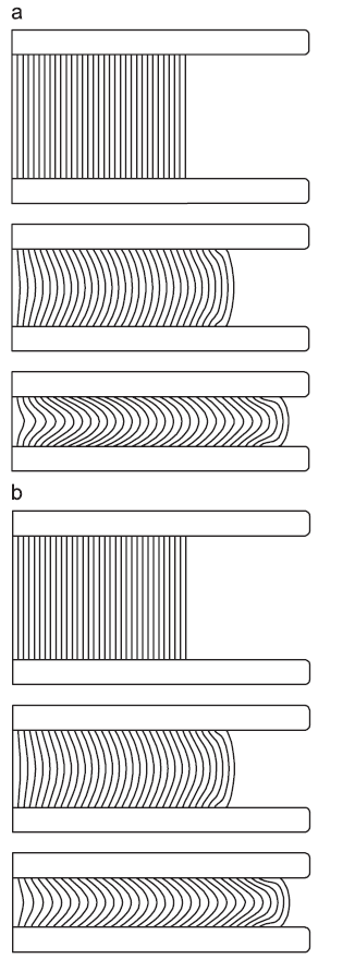
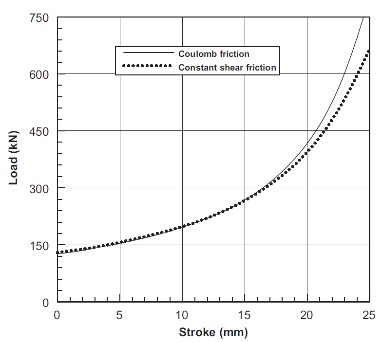
Figure 6: Stroke – forming load curves of the ring compression with large aspect ratio and large ratio of the contact region
3. Hot strip rolling
Hot strip rolling is a representative example of a process with a large aspect ratio and a large contact ratio. Thus, it is the extreme case in studying the two friction laws. The parameters used for the hot strip rolling process were as follows:
- Roll diameter: 400 mm
- Initial strip thickness: 2 mm
- Reduction ratio: 40%
- Strain rate hardening exponent: 0.195
- Roll speed: 1256.64 mm/s
Figure 7 shows the relative velocity of the material with respect to the roll along the roll-material interface. It can be seen that results obtained for m=1.0 are nearly the same as for µ = 0.2. This can also be observed in Figure 8, which shows the roll pressure distribution or the friction hill.
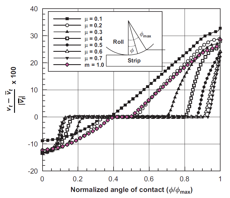
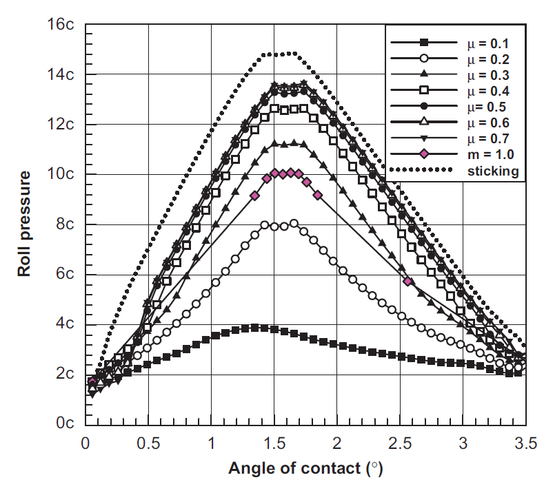
Figure 8: Variation of roll pressure with frictional conditions
The predicted results demonstrate that the sticking region increases as the Coulomb friction coefficient increases but that the constant shear friction law cannot predict the distinct sticking phenomena even with the maximum value of m = 1.0. Figure 8 shows that the constant shear friction law imposes excessive friction around the exit and entry but that it reduces the friction in the middle region near the neutral point. Therefore, it was concluded that the friction evaluation curves are irrelevant to hot strip rolling.
This brings us to the end of the first article of the friction series. In the next article, the following three processes will be discussed.
- Ring gear forging
- Cold extrusion of long billet
- Simultaneous expansion and shrinkage of a long pipe
Hope you like reading this article. If you find this useful, please do share it and spread the word.
See
you soon in the next article.
Note:
The series of two articles are a summary of the paper titled “Effect of
friction laws on metal forming simulations” published on Tribology International
42 (2009) 311-319.

