Consideration on metal flow lines in forging and their prediction in ring rolling after forging
페이지 정보
작성일posted onLink
본문
Consideration on metal flow lines in forging and their prediction
in ring rolling after forging
Metal flow lines (MFLs) or fiber flow lines are one of
major factors affecting product liability and structural rigidity. It is thus
essential to test the MFLs of a forging to evaluate its soundness in terms of metal
forming because MFLs inherently contain the history of plastic deformation of
metal formed product. They are thus the first barometer of structural
performance of bearing or gear parts which sustain extreme load conditions.
In
this blog post, a four-stage combined metal forming process of a hub
bearing, the final ring rolling stage after three-stage forging stages, is presented
with emphasis on MFL. The predictions are then compared with experiments.
Figure 1 is the process design for fabricating a hub bearing race which has hot upsetting, hot backward extrusion, hot piercing and hot ring rolling, respectively.
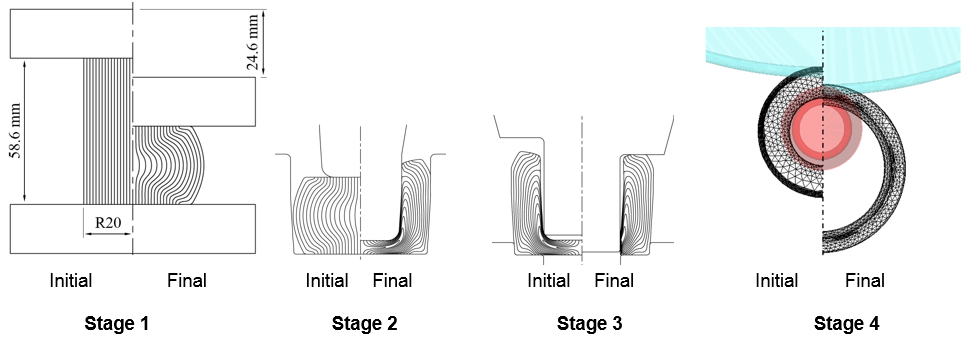
Process conditions and simulation information are as follows: Material is STB2 [2]. An isothermal analysis was conducted with initial material temperature of 1130℃. Coefficient of Coulomb friction at the material-die interface was assumed to be 0.3 and the forming velocity to be 200mm/s. The number of tetrahedral elements was controlled between 30000 (forging) and 60000 (ring rolling) for the entire solution domain.
Note
that for improved MFLs the flow stress at very low strain rate was constrained
not to become below a certain value, which is a kind of initial yield stress at
the room temperature. Figure 2 shows predictions at some important strokes.
As can be seen in the figure, the cut MFLs generated in the piercing stage remain on inner surface of the ring rolled part where bearing balls will contact. The deep valley of MFLs formed in the backward stage became much deeper owing to the ring rolling process.
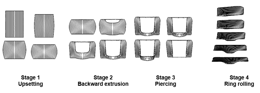
Figure 2: Visualization of metal flow
lines
Consequently, the process design in Figure 1 should be much improved [1], especially for fabricating the blank for ring rolling because the MFLs cannot be improved during ring rolling. Figure 3 compares the prediction of MFLs with experiments for the final ring rolled material, revealing that they are in good agreement with each other.
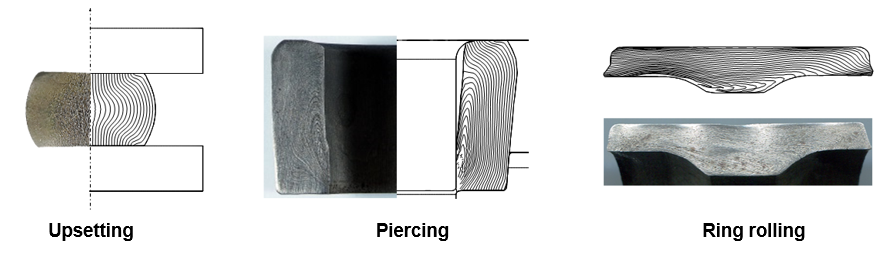
Figure 3: Comparison of predictions and experiments
The three-dimensional MFLs were traced throughout the entire process without any user intervention. This innovative approach of predicting MFLs for complicated three-dimensional metal forming processes will help process engineers obtain improved process designs in metal forming.
Do follow us on LinkedIn to stay updated and know more interesting simulation examples from a wide variety of metal forming processes.
References:
[1]
S. Ito, N. Tsushima, H. Muro, 1982, Accelerated rolling contact fatigue test by
a cylinder-to-ball, Rolling contact fatigue testing of bearing steel ASTM STP
771, American Society for Testing and Materials, pp. 125-135.
[2]
M.H. Choi, H.T. Jin, M.S. Joun, 2015, Consideration on metal flow lines in
forging and their prediction in ring rolling after forging, ASPF 2015
[3]
H.T. Jin, M.H. Choi, M.S. Joun, 2015, Effect of flow stress, friction,
temperature and velocity on finite element predictions of metal flow lines in
forging, ASPF 2015